Offset Curves
The Offset declaration can be used to create a planar offset curve or face from an edge that is offset by a given positive or negative offset distance.
# Created in DeclaraCAD
from declaracad.occ.api import *

enamldef Assembly(Part):
    Rectangle:  r1:
        color = 'red'
        # Center on origin
        position = (-width/2, -height/2)
        height = 10
        width = 20
        rx = 1
    Offset: o1:
        color = 'blue'
        shape = r1
        offset = 1
    Offset: o2:
        color = 'lime'
        shape = r1
        offset = -1

    # For reference
    Line: xaxis:
        color = 'black'
        direction = (1, 0)
    Line: yaxis:
        color = 'black'
        direction = (0, 1)
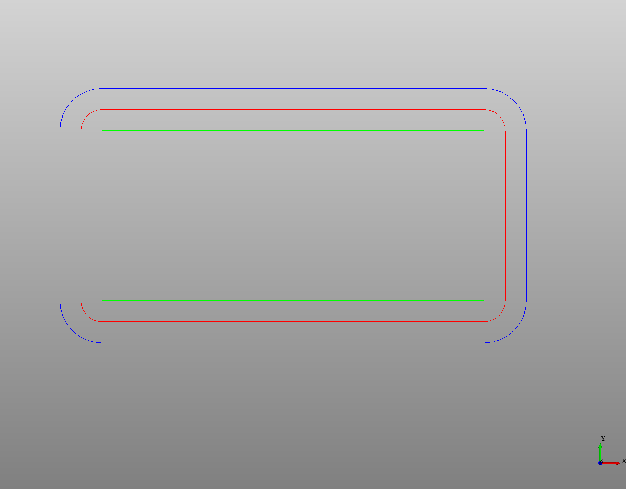
Notice how the positive and negative offset distances produce different shapes. This also depends on the "path direction" of the wire.
Attempting to use Offset on shapes that are not in the same plane will give an error. Also offsetting a face with holes in it can also give errors.
Note: The shape being offset must be able to be converted to a plane (it must have a normal). A single line segment for example has no normal. To offset a single line segment split it into two segments and make a wire from it.
Normal distance
An offset and shift along the plane normal can be completed in one Offset operation by specifying the normal_distance. For example a circle with a normal of the Z axis with normal_distance = 1 will be shifted "up" by 1 in the Z direction.
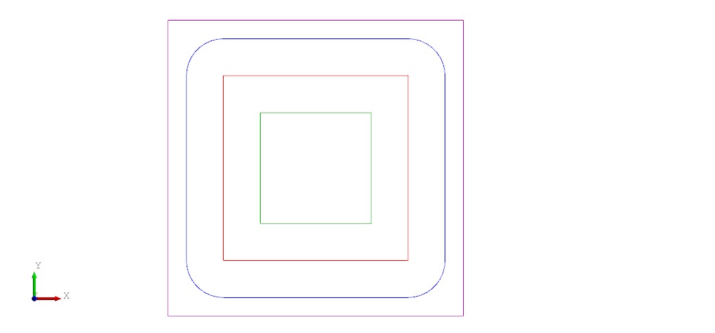
Join type
In certain situations you might not want the offset curve to produce arcs when expanding corners. The join_type defaults to arc but can be set to either tangent or intersection to change how the offset curves are joined together. In the screenshot below the blue square has a positive offset from the red square with the default join_type = "arc" while the purple square has a positive offset with join_type = "intersection". The green square has a negative offset and is unchanged.
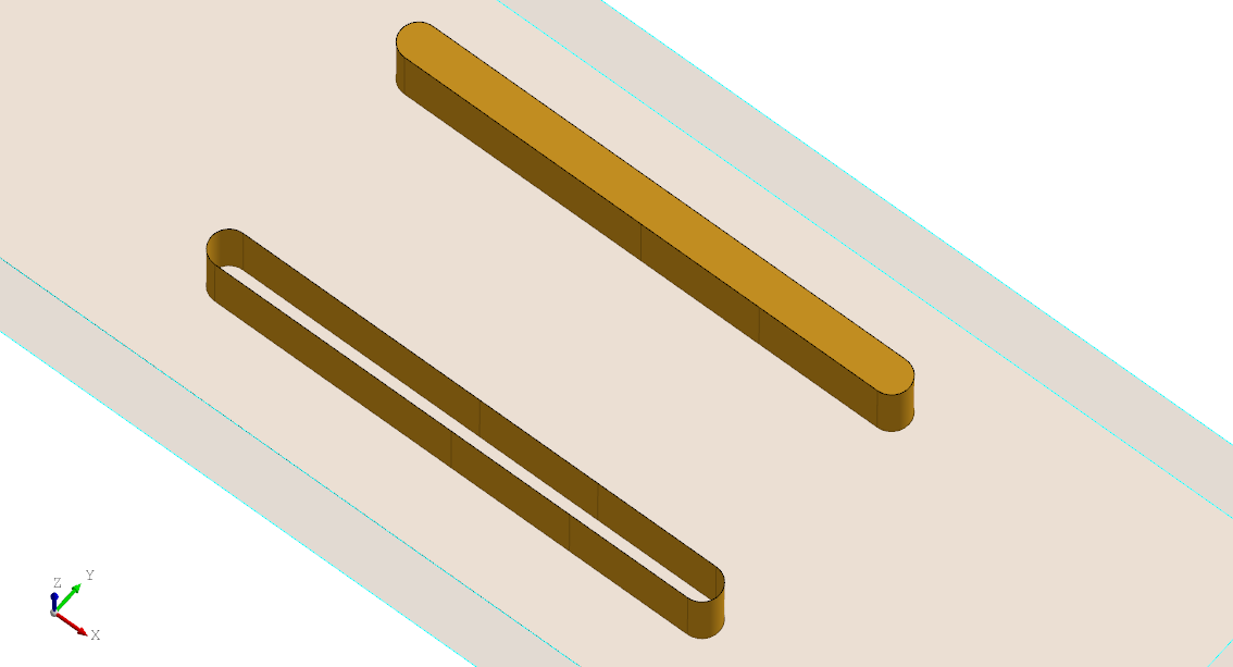
As face
Use as_face = True to convert the result into a face otherwise it will be a wire. This allows you to skip an extra Face node. The following example shows the difference when extruding a face vs a wire.
enamldef SimplePart(Part):

    Box: stock:
        transparency = 0.8
        position = (-dx/2, -dy/2,  -dz)
        dx = 100
        dy = 40
        dz = 10
    Extrude:
        vector = (0, 0, -stock.dz/2)
        Offset:
            offset = 1.5
            as_face = True
            Polyline:
                points = [(-20, 10), (0, 10), (20, 10)]
    Extrude:
        vector = (0, 0, -stock.dz/2)
        Offset:
            offset = 1.5
            Polyline:
                points = [(-20, -10), (0, -10), (20, -10)]
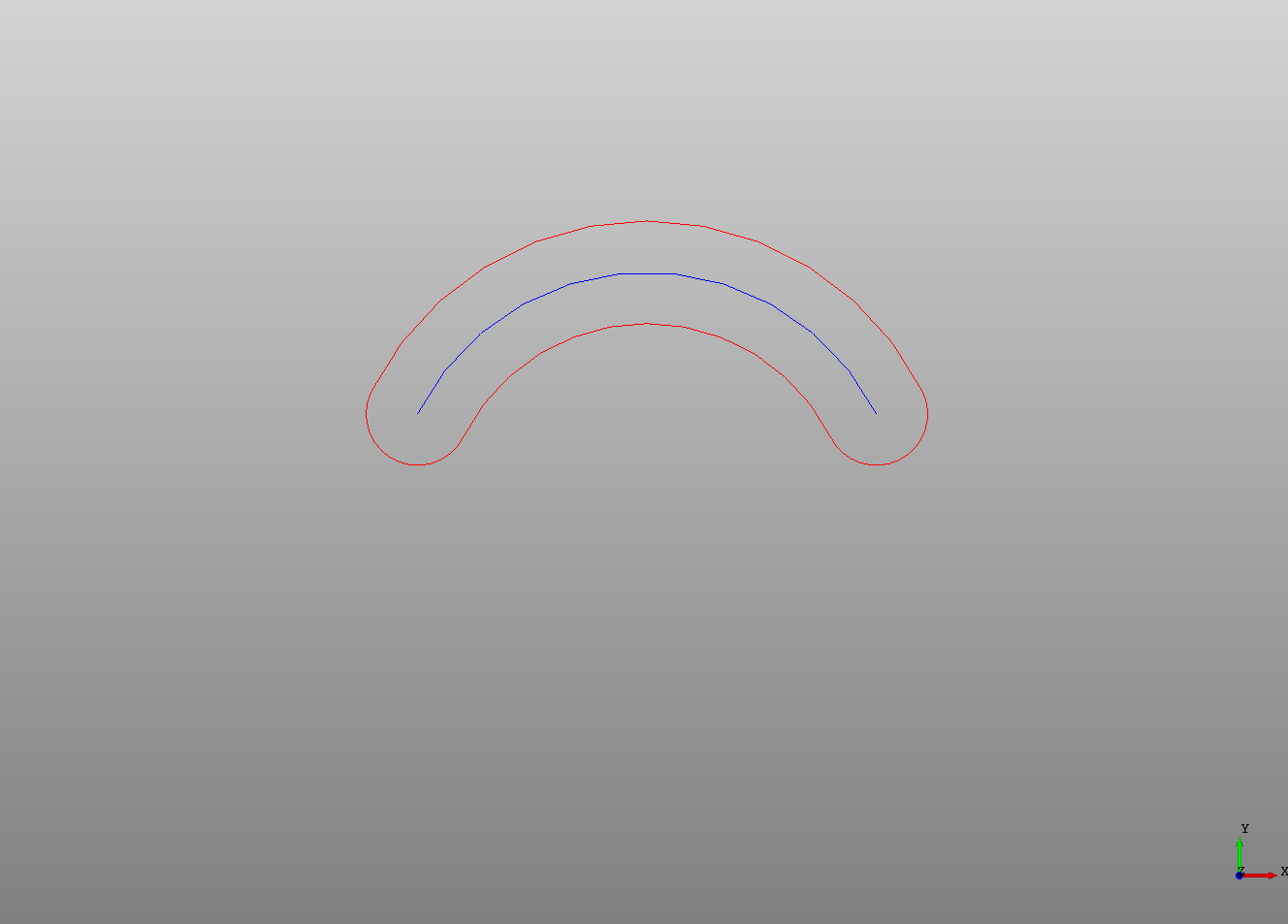
Slots
An Offset can be used on to create slots to cut out from a part. Just draw the path the slot should follow and set the offset to the radius of the slot. If a shape is added as a child of the Offset that shape will be offset.
# Created in DeclaraCAD
from declaracad.occ.api import *

enamldef Assembly(Part):
    Offset:
        color = 'red'
        offset = 1
        Arc: arc:
            radius = 5
            points = [(2, 1), (-2, 1)]

    # A copy to show the original path
    Transform:
        color = 'blue'
        shape = arc