Assemblies
Assemblies in DeclaraCAD are built by composing Part declarations. Typically each part is individually designed by itself and then imported and located in the correct orientation relative to the parent part.
Each Part declaration has it's own local coordinate system which is defined by the position, direction, and rotation like any shape and additional transformations supplied to the transform attribute. The transform attribute takes a list of TransformOperation items (eg Translate, Scale, Rotate, or Mirror) similar to the Transform node's operations list.
When one Part is nested in another, the local coordinate system is multiplied by the parent's coordinate system to position itself within the global coordinate system. This means all nested parts are transformed as a single unit when the assembly / parent part is moved around.
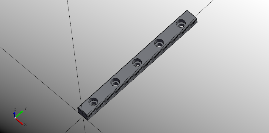
This is best explained by an example. Below is a part definition for a 9mm wide 100mm long linear rail.
# Created in DeclaraCAD
from math import floor
from declaracad.occ.api import *
from declaracad.parts.display import Axis

enamldef NX5Rail(Part): rail:
    attr show_chamfers: bool = True
    attr length = 100
    attr width = 9
    attr height = 6.5
    attr hole_spacing = 20
    func get_hole_positions(length, hole_spacing):
        n = floor(length/hole_spacing)
        padding = (length-(n-1)*hole_spacing)/2
        return [padding+i*hole_spacing for i in range(n)]
    Cut:
        material = 'steel'
        Chamfer:
            attr faces = core.topology.faces
            attr edges = core.topology.edges
            attr e = [1, 71, 41, 56]
            operations = [
                (0.5, faces[4]),
                (0.5, faces[11]),
                (0.3, edges[59], faces[10]),
                (0.3, edges[41], faces[5]),
                (0.3, edges[1], faces[0]),
                (0.3, edges[71], faces[12]),
            ]
            disabled = not show_chamfers
            Cut: core:
                Box:
                    position = (-dx/2, 0)
                    dx = width
                    dy = length
                    dz = height

                Extrude: track:
                        vector = (0, length, 0)
                        Face:
                            Rectangle: track_profile:
                                position = (rail.width/2-width/2, 0, rail.height-2.5-height/2)
                                direction = (0, 1, 0)
                                width = 1.75
                                height = 1
                                rx = height/2
                Transform:
                    shape = track
                    position = (-rail.width, 0)
        Looper:
            iterable = get_hole_positions(rail.length, rail.hole_spacing)
            Cylinder:
                position = (0, loop.item)
                height = rail.height
                radius = 3.65/2
            Cylinder:
                position = (0, loop.item, rail.height-self.height)
                radius = 3
                height = 3.5
        Box: # Direction mark?
            position = (3/2, 0)
            dx = 0.5
            dy = rail.length
            dz = 0.1

enamldef Assembly(Part):
    Axis:
        pass
    NX5Rail: rail:
        pass
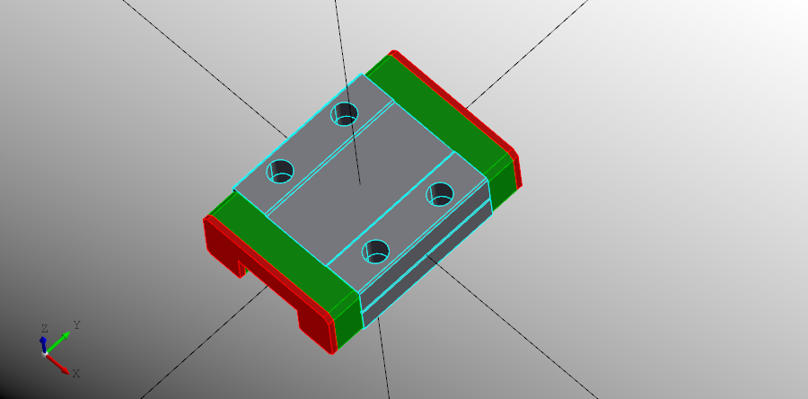
In the same file or another file we can create the carriage part.
# Created in DeclaraCAD
from math import floor
from declaracad.occ.api import *
from declaracad.parts.display import Axis

enamldef NX5Carriage(Part): part:
    attr bumper = 4
    attr width = 20
    attr length = 20
    attr height = 8
    attr offset = 2.5
    attr cutout = 9.25
    attr hole_spacing = (15, 10)
    attr hole_depth = 6
    attr bumper_length = 4
    attr cap_length = 0.75
    attr total_length << length+bumper_length*2+cap_length*2
    func get_hole_positions(w, h, d):
        x, y = w/2, h/2
        z = part.height/2-d
        return [(x, y, z), (x, -y, z), (-x, y, z), (-x, -y, z)]

    Chamfer:
        #disabled = True
        material = 'steel'
        attr faces = carriage.topology.faces
        attr edges = carriage.topology.edges

        operations = [
            (0.25, edges[1], faces[2]),
            (0.25, edges[22], faces[2]),
            (0.25, edges[79], faces[14]),
            (0.25, edges[83], faces[14]),
            (0.25, edges[59], faces[9]),
            (0.25, edges[3], faces[0]),
        ]

        Cut: carriage:
            transparency = 0.4
            Box: base:
                position = (-dx/2, -dy/2, -height/2)
                dx = width
                dy = length
                dz = height
            Box:
                position = (-dx/2, -dy/2, -height/2)
                dx = cutout
                dy = length
                dz = height/2
            Box:
                position = (-dx/2, -dy/2, height/2-dz)
                dx = cutout
                dy = length
                dz = 0.25+1e-5
            Looper:
                iterable = get_hole_positions(hole_spacing[0], hole_spacing[1], hole_depth)
                Cylinder:
                    position = loop.item
                    height = hole_depth
                    radius = 3/2
            Box: # Direction mark?
                position = (width/2-dx, -dy/2, -dz)
                dx = 0.2
                dy = part.length
                dz = 0.4
    Chamfer: bumper:
        material = 'plastic'
        color = 'green'

        attr edges = self.children[0].topology.edges
        attr faces = self.children[0].topology.faces
        operations = [
            (0.75, edges[1], faces[0]),
            (0.5, edges[3], faces[0]),
            (0.75, edges[14], faces[9]),
            (0.5, edges[41], faces[9]),
            (0.25, edges[25], faces[5]),
            (0.25, edges[39], faces[7]),
        ]
        #disabled = True
        Cut:
            Box: bumper_core:
                attr offset = 0.25
                position = (-dx/2, length/2, -height/2)
                dx = width - offset
                dy = bumper_length
                dz = height - offset
            Box:
                position = (-dx/2, length/2, -height/2)
                dx = cutout
                dy = bumper_length
                dz = height/2

    Transform:
        material = 'plastic'
        color = 'green'
        shape = bumper
        position = (0, -length-bumper_length, 0)

    Chamfer: end_cap:
        material = 'plastic'
        color = 'red'

        attr edges = self.children[0].topology.edges
        attr faces = self.children[0].topology.faces
        operations = [
            (0.75, edges[1], faces[0]),
            (0.5, edges[3], faces[0]),
            (0.75, edges[14], faces[9]),
            (0.5, edges[41], faces[9]),

            (0.25, edges[25], faces[5]),
            (0.25, edges[39], faces[7]),
        ]
        #disabled = True
        Cut:
            Box:
                attr offset = 0.25
                position = (-dx/2, length/2+bumper_length, -height/2)
                dx = width - offset
                dy = cap_length
                dz = height - offset
            Box:
                position = (-dx/2, length/2+bumper_length, -height/2)
                dx = cutout
                dy = cap_length
                dz = height/2
    Transform:
        material = 'plastic'
        color = 'red'
        shape = end_cap
        position = (0, -length-2*bumper_length-cap_length, 0)

enamldef Assembly(Part):
    Axis:
        pass
    NX5Carriage: rail:
        pass
To combine these into an assembly just make another Part which embeds the two parts like this.
enamldef NX5RailAssembly(Part): part:
    #: Parametric
    attr t = 0.0
    attr dt = 0.01
    #: Limit to end of rail
    attr padding = 5
    alias rail
    alias carriage

    attr start = carriage.total_length/2+padding
    attr available = rail.length - carriage.total_length - 2*padding
    func get_position(t):
            # Compute carriage position
        t = max(0, min(1, t))
        return (0, start+t*available, rail.height)
    NX5Rail: rail:
        pass
    NX5Carriage: carriage:
        position << get_position(t)

enamldef Assembly(Part):
    Axis:
        pass
    NX5RailAssembly: r1:
        t = 0.5
The NX5RailAssembly embeds both the NX5Rail and NX5carriage as parts within the part. It then defines a function to compute the carriage position and supplies a parameter t to position it within the rail.
This parameter can be updated with a timer to animate the movement as shown below. DeclaraCAD will walk the part definition tree and recompute the locations of all nested parts. If the NX5RailAssembly is transformed to another position or direction the position calculation does not need modified.
Caching assemblies
As DeclaraCAD models are script based by default the entire model is re-evaluated on every change. For complex parts or assemblies it can start to take a progressively longer amount of time to run reducing productivity. To help address this, the Part declaration now includes cached, cache_key, and reload members.
Note: Using
cached = Trueby design "leaks" memory. If you move to another file or keep changing the cache keys it, the old models will still be in the cache. You can manually wipe them out if needed by modifying thePart.cached_parts.
When a part has cached = True set it will render an embedded part and store it in the static Part.cached_parts dictionary under a key using of f"{cls.__name__}.{cache_key}. The next time the script is run it will lookup the part in the cache and, if present, re-render the same part. If you need to invalidate the cache, set reload = True and it will re-generate the part.
If you re-use the same cached Part instance (eg with different options or position) multiple times you need to specify a value for cache_key or it will simply render the same part.
Note: A Part with
cached=Truebehaves like enaml'sIncludeblock. Instead of rendering it's declaration it inserts the cached part into the parent's tree. If you need to reference items from the part you have to use thecachepart member to access the reference. This is still undergoing development may change in the future.