Circuit
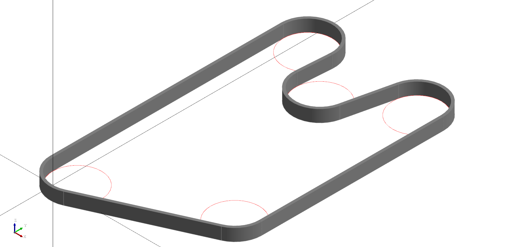
The Circuit node is used create a wire following the path around a set of circles. Typically this is used for creating belts or chains around a set of gears or pulleys.
Specify the circles attribute which takes a list of circles to build the circuit from. Circles can take the form of a tuple in the format of (radius, position) or be an instance of a Circle node. All circles must be in a single plane. An offset value can be provided to add space around positive or negative turns as shown below. The offset value only applies to circles with the same side, eg a negative offset only is added to internal circles (those that also have a negative radius).
Note: A circle can be given a negative radius to indicate the path should go around the "inside". The
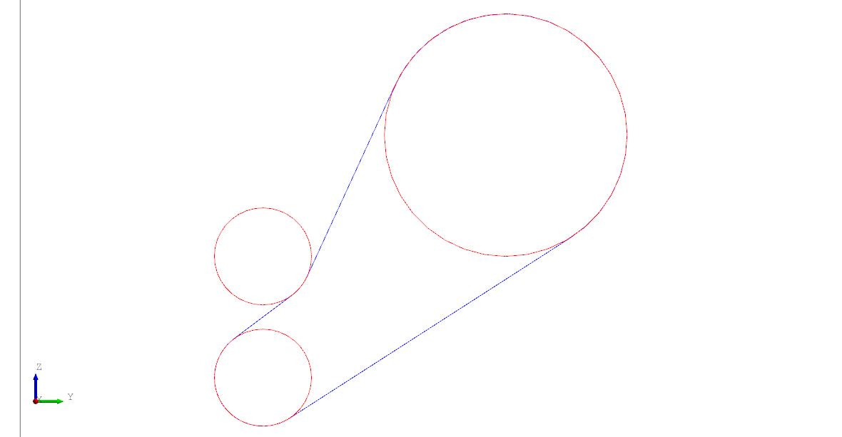
reverse=Trueparameter (or a boolean in the tuple) will tell the solver to reverse the arc direction.
# Created in DeclaraCAD
from declaracad.parts.display import Axis
from declaracad.occ.api import *

enamldef Assembly(Part):
    Axis:
        pass

    Include:
        objects = belt.circles

    Extrude:
        vector = (0, 0, 1)
        color = '#333'
        Loft:
            Circuit: belt:
                offset = 0.2
                circles = [
                    (2,  (1, 1)),
                    (2,   (10, 5)),
                    (2,   (10, 20)),
                    (-2,   (5, 17)),
                    (2,   (1, 20)),
                ]
            Circuit:
                offset = -0.2
                circles = belt.circles

An example showing using Circle directly and specifying the reverse parameter. Alternatively you can set reverse = True on the Circuit instead of each circle.
# Created in DeclaraCAD
from declaracad.parts.display import Axis
from declaracad.occ.api import *

enamldef Assembly(Part):
    Axis:
        pass
    Include:
        objects = idler.circles
    Circuit: idler:
        color = 'blue'
        circles = [
           Circle(radius=2, reverse=True, position=(0, 10, 10), direction=(1, 0, 0)),
           Circle(radius=-2, reverse=True, position=(0, 10, 15), direction=(1, 0, 0)),
           Circle(radius=5, reverse=True, position=(0, 20, 20), direction=(1, 0, 0)),
        ]

Note: If only two circles are given it will use the
positionanddirectionof the first circle to define the "normal" plane.
