Building Profiles
Now that most of the primitive sketching declarations have been shown let's build a simple profile.
For this tutorial we're going to build a THK SHS Standard Rail profile.
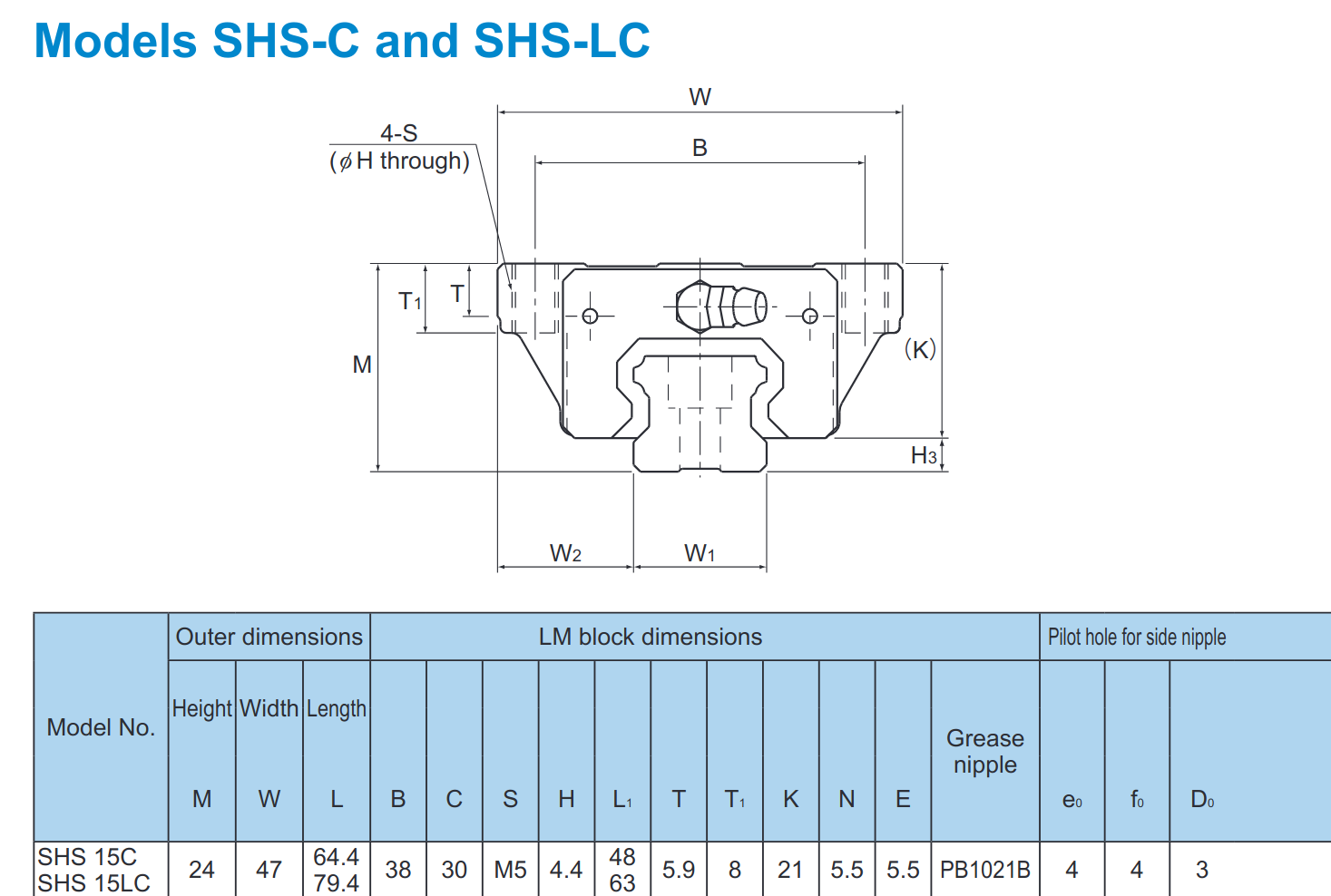
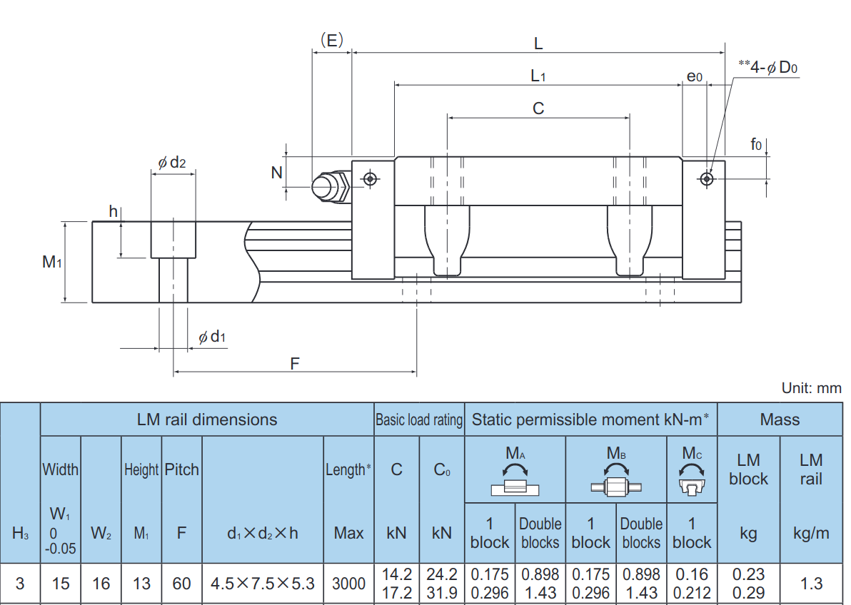
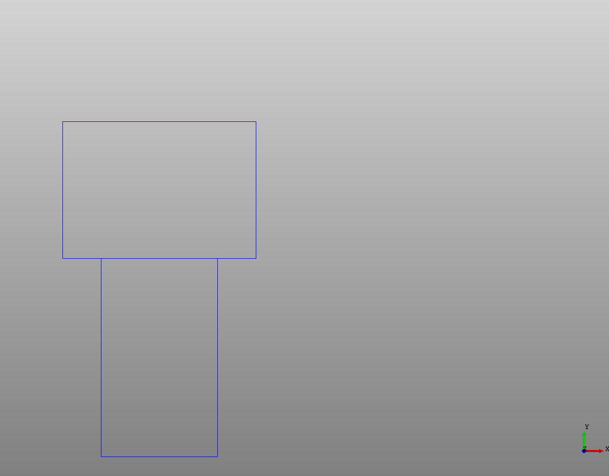
First let's start with the bolt profile as a reference. Copying in the values from d1 x d2 x h just make two rectangles for the bolt profile:
# Created in DeclaraCAD
from declaracad.occ.api import *

enamldef BoltProfile(Part):
    Rectangle:
        color = 'blue'
        position = (-width/2, 13-5.3)
        width = 7.5
        height = 5.3
    Rectangle:
        color = 'blue'
        position = (-width/2, 0)
        width = 4.5
        height = 13 - 5.3

enamldef Assembly(Part):
    BoltProfile:
        pass
Now to do the rail I'm going to start with the origin at bottom center of the rail and work in the XY plane. Also, as is done in the tutorial, I'm going to only profile half of the shape then mirror over the other half.
Most of the rail is straight lines except for where the balls roll, so I'm going to start with a Polyline and work around until we get to the arc. Since not all of the dimensions are given I'm going to guestimate some here, then adjust.
# Created in DeclaraCAD
from declaracad.occ.api import *

enamldef Profile(Wire):
    attr w1 = 15
    attr m1 = 13
    attr h3 = 3
    attr h = 5.3
    attr d1 = 4.5
    Polyline: p1:
        attr c0 = d1 / 15 # Chamfer distance inside bottom corner
        attr c1 = h3/6 # Chamfer distance bottom corner
        attr c2 = h3/2 # Chamfer distance top of h3 corner
        attr c3 = h3/6 # Chamfer distance top of h3 corner
        attr d1 = h3 * 3/2
        points = [
            (0, h3/10),
            (d1/2-c0, h3/10), # Inner bottom grove
            (d1/2, h3/10-c0),
            (d1/2, 0),
            (w1/2 - c1,0), # Bottom outside chamfer
            (w1/2, c1),
            (w1/2, h3), # At H3
            (w1/2 - c2, h3 + c2),
            (w1/2 - c2, h3 + c2 + d1),
            (w1/2 - c2 + c3, h3 + c2 + d1 + c3),
        ]

enamldef BoltProfile(Part):
    Rectangle:
        color = 'blue'
        position = (-width/2, 13-5.3)
        width = 7.5
        height = 5.3
    Rectangle:
        color = 'blue'
        position = (-width/2, 0)
        width = 4.5
        height = 13 - 5.3

enamldef Assembly(Part):
    Profile:
        color = 'red'
    BoltProfile:
        pass
I'm using attr to define variables from the datasheet then adding points as I work around the profile, the points start at the bottom left then finish at the top before the curve starts.
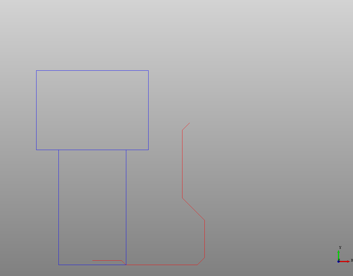
Now instead of using Arc which can be difficult to calculate (it's easy here actually), I'm just using a cubic Bezier curve with a fixed r to define an arc and adding to the point of the last part of the wire.
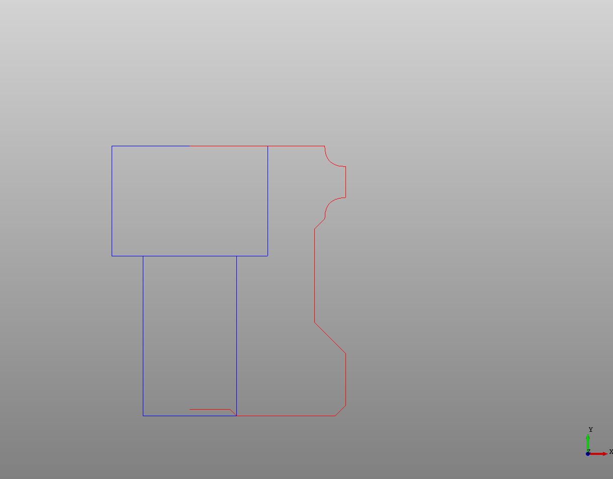
After some adjusting (to d1) it finally looks like the ratio looks correct and it ended up right at the top of the bolt profile where it should. Now let's mirror it to create a full profile. To do this we use the Transform node and the Mirror operation.
# Created in DeclaraCAD
from declaracad.occ.api import *

enamldef Profile(Wire):
    attr w1 = 15
    attr m1 = 13
    attr h3 = 3
    attr h = 5.3
    attr d1 = 4.5
    Polyline: p1:
        attr c0 = d1 / 15 # Chamfer distance inside bottom corner
        attr c1 = h3/6 # Chamfer distance bottom corner
        attr c2 = h3/2 # Chamfer distance top of h3 corner
        attr c3 = h3/6 # Chamfer distance top of h3 corner
        attr d1 = h3 * 3/2
        points = [
            (0, h3/10),
            (d1/2-c0, h3/10), # Inner bottom grove
            (d1/2, h3/10-c0),
            (d1/2, 0),
            (w1/2 - c1,0), # Bottom outside chamfer
            (w1/2, c1),
            (w1/2, h3), # At H3
            (w1/2 - c2, h3 + c2),
            (w1/2 - c2, h3 + c2 + d1),
            (w1/2 - c2 + c3, h3 + c2 + d1 + c3),
        ]
    Bezier: b1:
        attr p = p1.points[-1] # Last point
        attr r = h3/3
        points = [
            p,
            p + (0, r),
            p + (r, r),
        ]
    Segment: s1:
        attr p = b1.points[-1] # Last point
        points = [p, p + (0, h3/2)]
    Bezier: b2:
        attr p = s1.points[-1] # Last point
        attr r = b1.r
        points = [
            p,
            p + (-r, 0),
            p + (-r, r),
        ]
    Segment: s2:
        attr p = b2.points[-1] # Last point
        points = [p, (0, m1)]

enamldef BoltProfile(Part):
    Rectangle:
        color = 'blue'
        position = (-width/2, 13-5.3)
        width = 7.5
        height = 5.3
    Rectangle:
        color = 'blue'
        position = (-width/2, 0)
        width = 4.5
        height = 13 - 5.3

enamldef Assembly(Part):
    BoltProfile:
        pass
    Wire:
        color = 'red'
        Profile: p1:
            pass
        Transform:
            operations = [Mirror(y=1)]
            shape = p1
Here the original Profile was given a name p1 and moved into a Wire. Then a Transform was added to the Wire with shape = p1 and an operation was added which tells it to mirror the shape about the y axis.
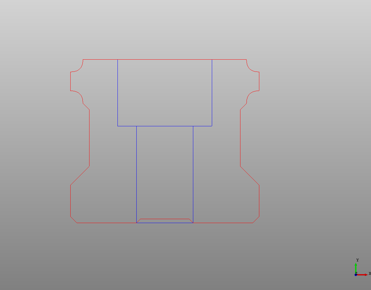
We can then take that Wire and make it a Face and extrude it into a rail!
# Created in DeclaraCAD
from declaracad.occ.api import *

enamldef Profile(Wire):
    attr w1 = 15
    attr m1 = 13
    attr h3 = 3
    attr h = 5.3
    attr d1 = 4.5
    Polyline: p1:
        attr c0 = d1 / 15 # Chamfer distance inside bottom corner
        attr c1 = h3/6 # Chamfer distance bottom corner
        attr c2 = h3/2 # Chamfer distance top of h3 corner
        attr c3 = h3/6 # Chamfer distance top of h3 corner
        attr d1 = h3 * 3/2
        points = [
            (0, h3/10),
            (d1/2-c0, h3/10), # Inner bottom grove
            (d1/2, h3/10-c0),
            (d1/2, 0),
            (w1/2 - c1,0), # Bottom outside chamfer
            (w1/2, c1),
            (w1/2, h3), # At H3
            (w1/2 - c2, h3 + c2),
            (w1/2 - c2, h3 + c2 + d1),
            (w1/2 - c2 + c3, h3 + c2 + d1 + c3),
        ]
    Bezier: b1:
        attr p = p1.points[-1] # Last point
        attr r = h3/3
        points = [
            p,
            p + (0, r),
            p + (r, r),
        ]
    Segment: s1:
        attr p = b1.points[-1] # Last point
        points = [p, p + (0, h3/2)]
    Bezier: b2:
        attr p = s1.points[-1] # Last point
        attr r = b1.r
        points = [
            p,
            p + (-r, 0),
            p + (-r, r),
        ]
    Segment: s2:
        attr p = b2.points[-1] # Last point
        points = [p, (0, m1)]

enamldef THKRail(Part):
    attr length = 1
    Prism:
        color = 'grey'
        vector = (0, 0, length)
        Face:
            Wire:
                Profile: p1:
                    pass
                Transform:
                    operations = [Mirror(y=1)]
                    shape = p1

enamldef Assembly(Part):
    THKRail:
        length = 100
The final product:
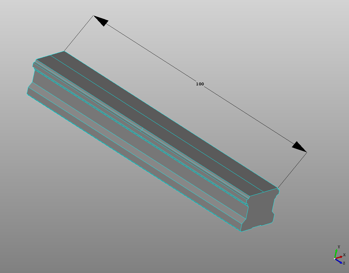
If this is saved as a file you can then import THKRail and use it in other files!
THK is a trademark of THK America, Inc.
