Meshing
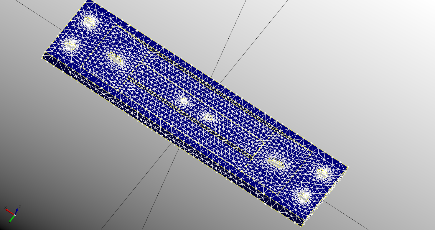
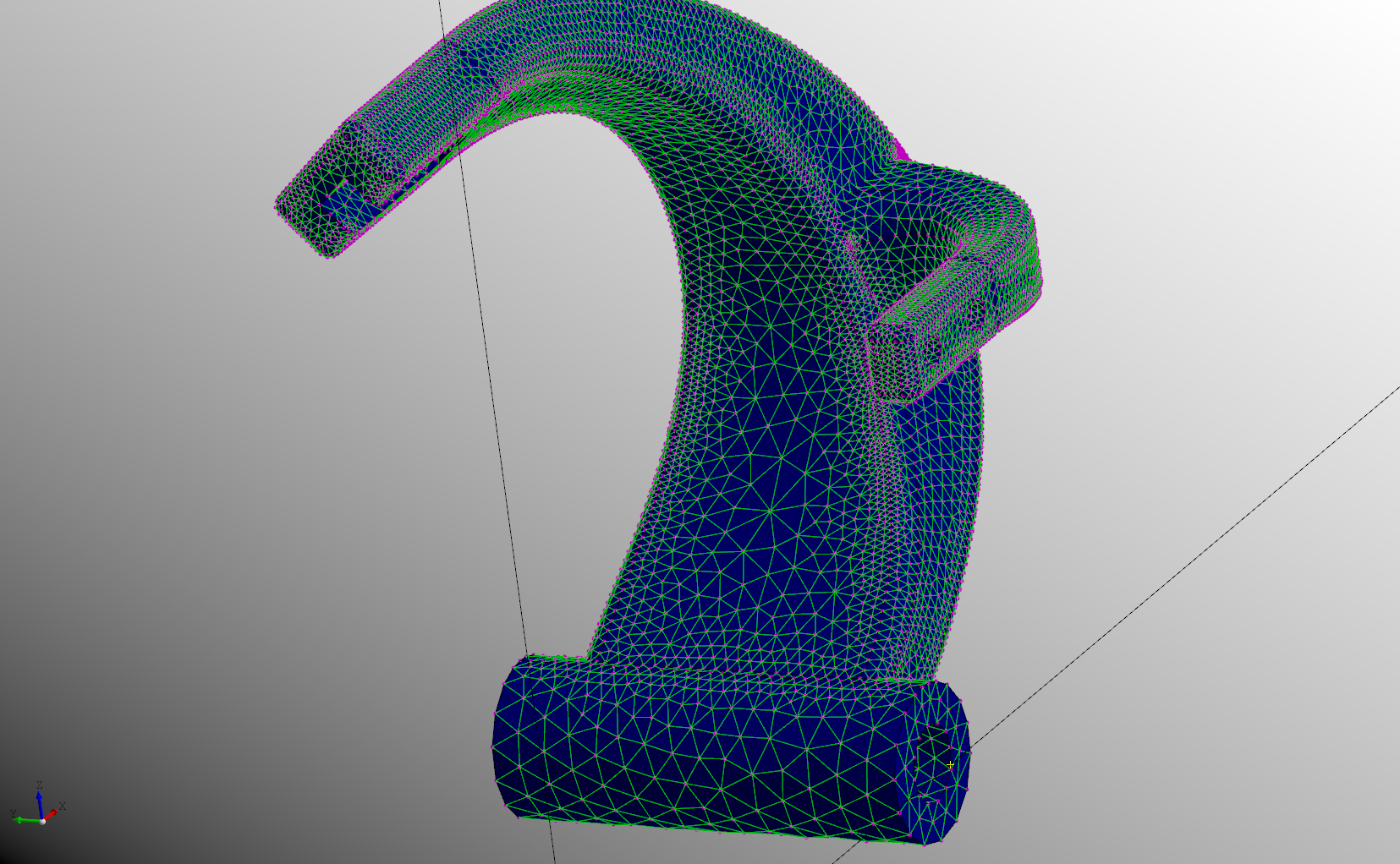
DeclaraCAD now supports meshing using the new Mesh declaration. Meshing is based on Salome's SMESH library and the pySMESH project.
Note: This feature is currently under development.
To create a mesh either embed the shape you want to mesh or supply it as the source attribute of the Mesh declaration. Meshing parameters currently need defined by overriding the prepare_mesh as shown below.
enamldef Assembly(Part):
    Axis:
        pass
    SupportBracket: bracket:
        display = False
    Mesh:
        source = bracket
        prepare_mesh => (gen, mesh, shape):
            hyp = NETGENPlugin_SimpleHypothesis_2D(0, gen)
            hyp.SetLocalLength(1)
            hyp.SetAllowQuadrangles(True)
            alg = NETGENPlugin_NETGEN_2D3D(1, gen)
            mesh.AddHypothesis(shape, 0)
            mesh.AddHypothesis(shape, 1)

Once the mesh has been generated the process_mesh function is called. This can be overridden to adjust nodes or do any post processing.
Note: Since meshing can take a lot of time you can temporarily disable mesh generation using
disabled = True
Mesh topology
The mesh topology differs from regular shapes in DeclaraCAD. A mesh is constructed of a set of Nodes and interconnected Elements. Elements have different types based on their linkage. To access the topology of the generated mesh simply use mesh.topology which has iterators over the nodes, elements, faces, and volumes of the mesh.
Each item in the mesh has a unique id to access it. DeclaraCAD caches these as they are used. Use mesh.find_<the type>(id) to lookup the node or element of the given ID.
The Node returned by the nodes iterator has fields id, position, color, description, mass, force, and data. The Element returned by the other iterators has fields id, nodes, description, front_color, back_color, material, and data.
Note: The nodes and elements
datafield can be used to store any user data on a node or element. The description field will be shown when the node is selected in the viewer.
Mesh style and colors
The mesh will default to colors specified using the beam_color, beam_size, edge_color, edge_size, node_color, node_size, node_type, and color attributes. The type of each can be found in the toolbox pane. For example:
    Mesh:
        source = arm
        node_color = "purple"
        node_size = 5
        node_type = "point"
        edge_color = "green"
        beam_color = "black"
                # etc ...

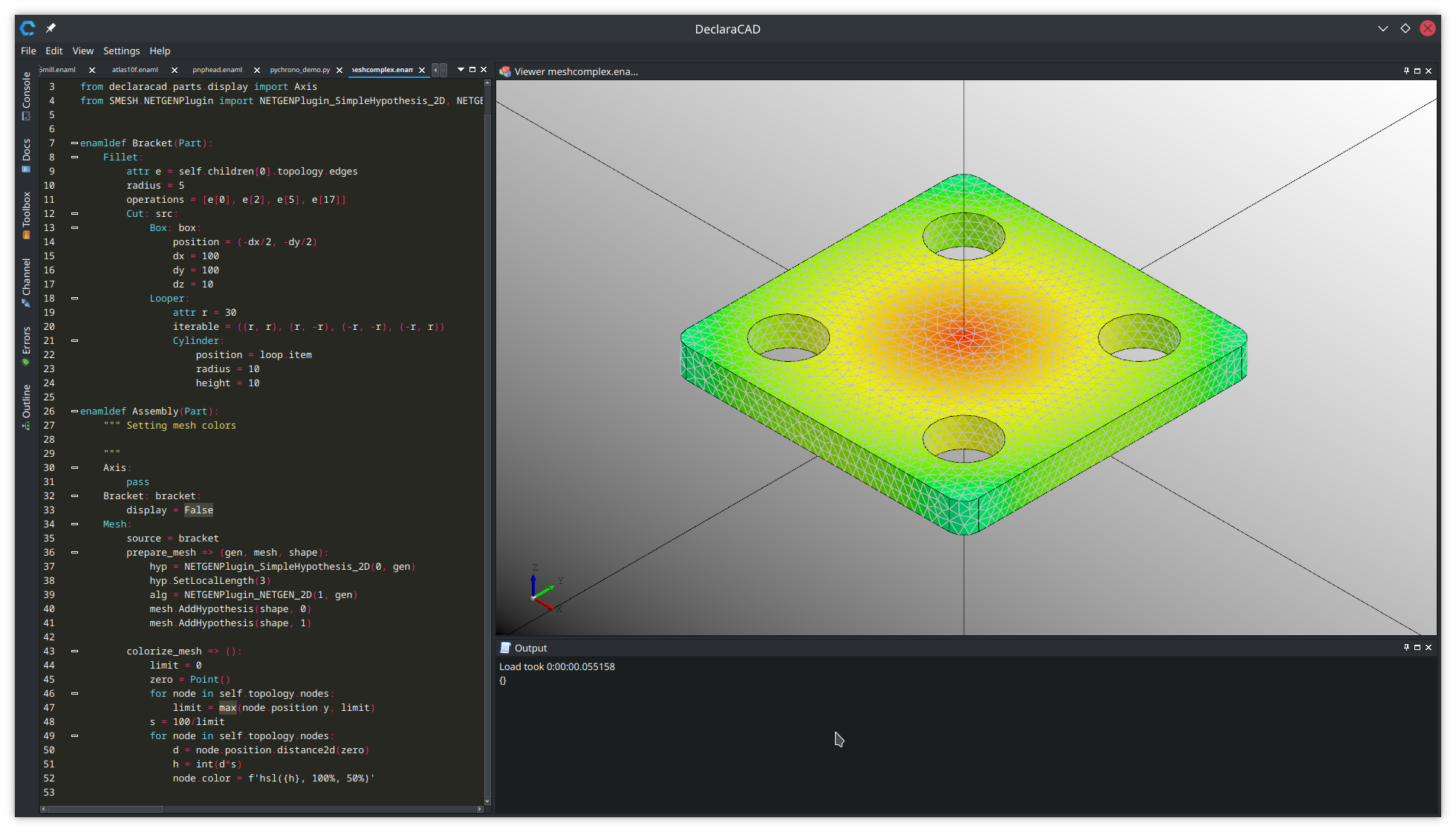
To set colors of individual mesh nodes or elements the colorize_mesh function can be overridden. It is invoked after the mesh has been generated and process_mesh has been called. Simply set the node color or element face colors as desired.
The example below sets the node colors to the 2d-distance from the z axis.
# Created in DeclaraCAD
from declaracad.occ.api import *
from declaracad.parts.display import Axis
from SMESH.NETGENPlugin import NETGENPlugin_SimpleHypothesis_2D, NETGENPlugin_NETGEN_2D


enamldef Bracket(Part):
    Fillet:
        attr e = self.children[0].topology.edges
        radius = 5
        operations = [e[0], e[2], e[5], e[17]]
        Cut: src:
            Box: box:
                position = (-dx/2, -dy/2)
                dx = 100
                dy = 100
                dz = 10
            Looper:
                attr r = 30
                iterable = ((r, r), (r, -r), (-r, -r), (-r, r))
                Cylinder:
                    position = loop.item
                    radius = 10
                    height = 10

enamldef Assembly(Part):
    """ Setting mesh colors

    """
    Axis:
        pass
    Bracket: bracket:
        display = False
    Mesh:
        source = bracket
        prepare_mesh => (gen, mesh, shape):
            hyp = NETGENPlugin_SimpleHypothesis_2D(0, gen)
            hyp.SetLocalLength(3)
            alg = NETGENPlugin_NETGEN_2D(1, gen)
            mesh.AddHypothesis(shape, 0)
            mesh.AddHypothesis(shape, 1)

        colorize_mesh => ():
            limit = 0
            zero = Point()
            for node in self.topology.nodes:
                limit = max(node.position.y, limit)
            s = 100/limit
            for node in self.topology.nodes:
                d = node.position.distance2d(zero)
                h = int(d*s)
                node.color = f'hsl({h}, 100%, 50%)'

Mesh export
The generated mesh can be exported to a file by setting the export_filename and specifying the export_type. The type can be:
- MED
- DAT
- UNV
- STL
- CGNS
- GMF
- SAUV
The exported file can be used other programs or loaded by your code to do further processing (ie analysis/simulation).
